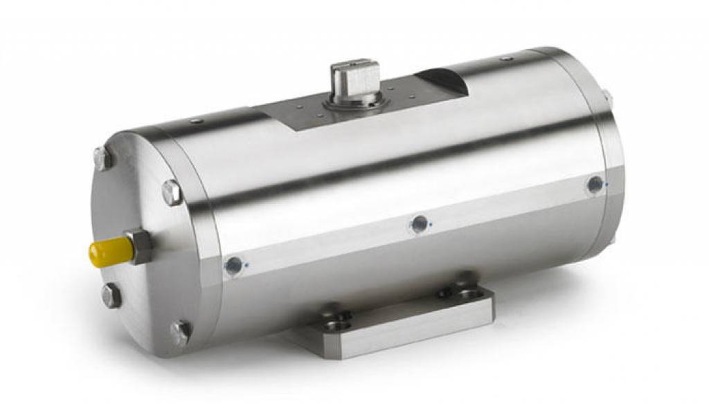
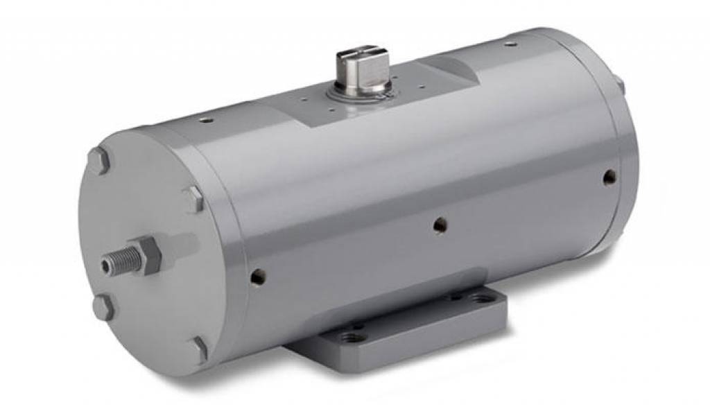
GD720-GD3840 (actuators can also be produced in carbon steel, with painting colours and details on request)
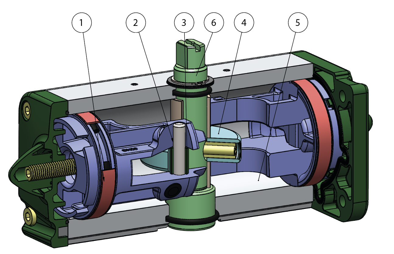
1.Energized and self-lubricated strips Less friction between piston and cylinder It prevents the bonding of the seal to the cylinder even after long periods of inactivity
2.Slots, bushes and pins made by steel with hardness higher than 50 HRC Higher resistance to the forces inside the actuator
3.Rolling friction between piston and slot Less friction
4.Scotch yoke with rolling friction (transforming rotary motion into linear motion using piston and shaft without teeths/gears) Reduced friction between piston and shaft with consequently less wear on the relevant parts Empowered Breakaway Torque (BTO & BTC) Smaller volume/size than rack and pinion actuators (with the same torque) therefore less space required for installation Less weight than the rack and pinion (-30% kg / Nm), with consequent savings on the construction sizing of the plant/equipment Lower air consumption compared to the rack and pinion actuators (-40% air cm3/Nm for Double Acting and -20% air cm3/Nm for Spring Return) therefore less load on the compressor or the possibility of using a smaller compressor's size. 5.Rolled cylinder Less wear of the energized ties thanks to the low roughness of the surface
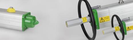
From sizes bigger than GD15, NAMUR interface for solenoid valve is already integrated. No need for extra plate.
100% in- house manufacturing process technology Maximum control and accuracy in all the stages of the manufacturing process
ATEX Certificate Installation is allowed in a potential explosive environment
Up to SIL 3 Certified Guarantee of the high level of functional safety.
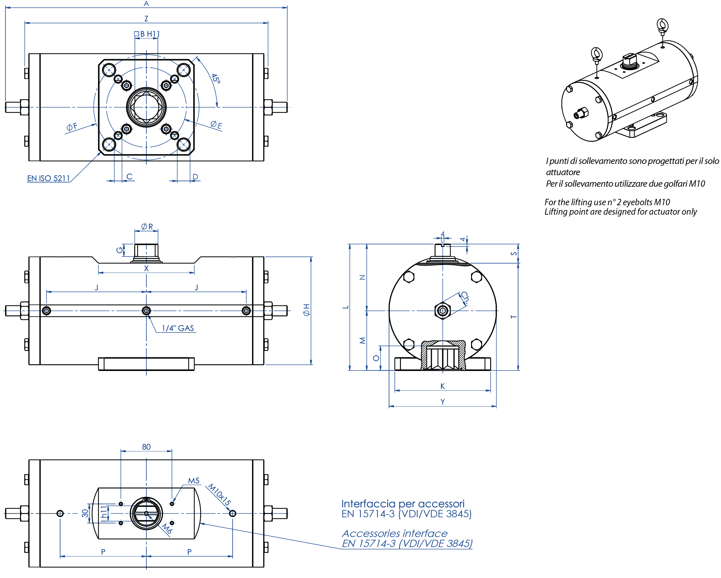
TECHNICAL FEATURES Torque from 720 Nm to 1920 Nm Mounting flange according to EN ISO 5211 F10 - F12 - F14 - F16 In compliance with EN 15714-3 Rotation angle: 92° (-1°, +91°) Torque: directly proportional to the air supply (see table - general catalogue pneumatic actuator GD) In the code of standard version GD actuators, it is indicated the breakaway torque in Nm at 5,6 bar air supply. ATEX version in conformity with directive 2014/34/EU
WORKING CONDITION Temperature: from -20°C to +80°C Air supply: 5,6 bar; maximum 8,4 bar Actuating media: filtered dry compressed air, not necessarily lubricated. In case of lubricated air, either non detergent oil, NBR compatible oil, must be used.
DATA SHEET
Code
GD0720416S
GD0960416S
GD1440424S
GD1440416S
GD1920416S
Spare seals
KGGSS123
KGGSS124
KGGSS125
KGGSS125
KGGSS126
Size
GD0720 F10/F12
GD0960 F12/F16
GD1440 F12
GD1440 F14
GD1920 F12/F16
A
401,5
441
524,8
524,8
562
B
27
36
36
36
46
C x depth
M10x11,5
M12x20
M12x18
M16x18
M12x23
D x depth
M12x11,5
M20x20
-
-
M20x23
ØE
102
125
125
140
125
ØF
125
165
-
-
165
G
19,5
19,5
19,5
19,5
18,5
ØH
156
169
188
188
211
I
22
24
27
27
32
J
138,5
156,3
179,5
179,5
192
K
115
150
130
130
150
L
178
198
216
216
237,7
M
78,5
93,5
101,5
101,5
114,7
N
99,5
104,5
114,5
114,5
123
O
29,5
38,5
38,5
38,5
48,5
P
116
135
160
160
160
ØR
31,8
36,5
41
41
46
S
30
30
30
30
30
T
148
168
186
186
207,7
X
150
150
150
150
150
Y
155
168
187
187
209
Z
345,8
381
433,8
433,8
469
Ch
24
24
30
30
30
Weight (Kg)
30
40
50,5
50,5
73
Air (dm³/cycle) (l/cycle)
3,7
4,8
7,7
7,7
10
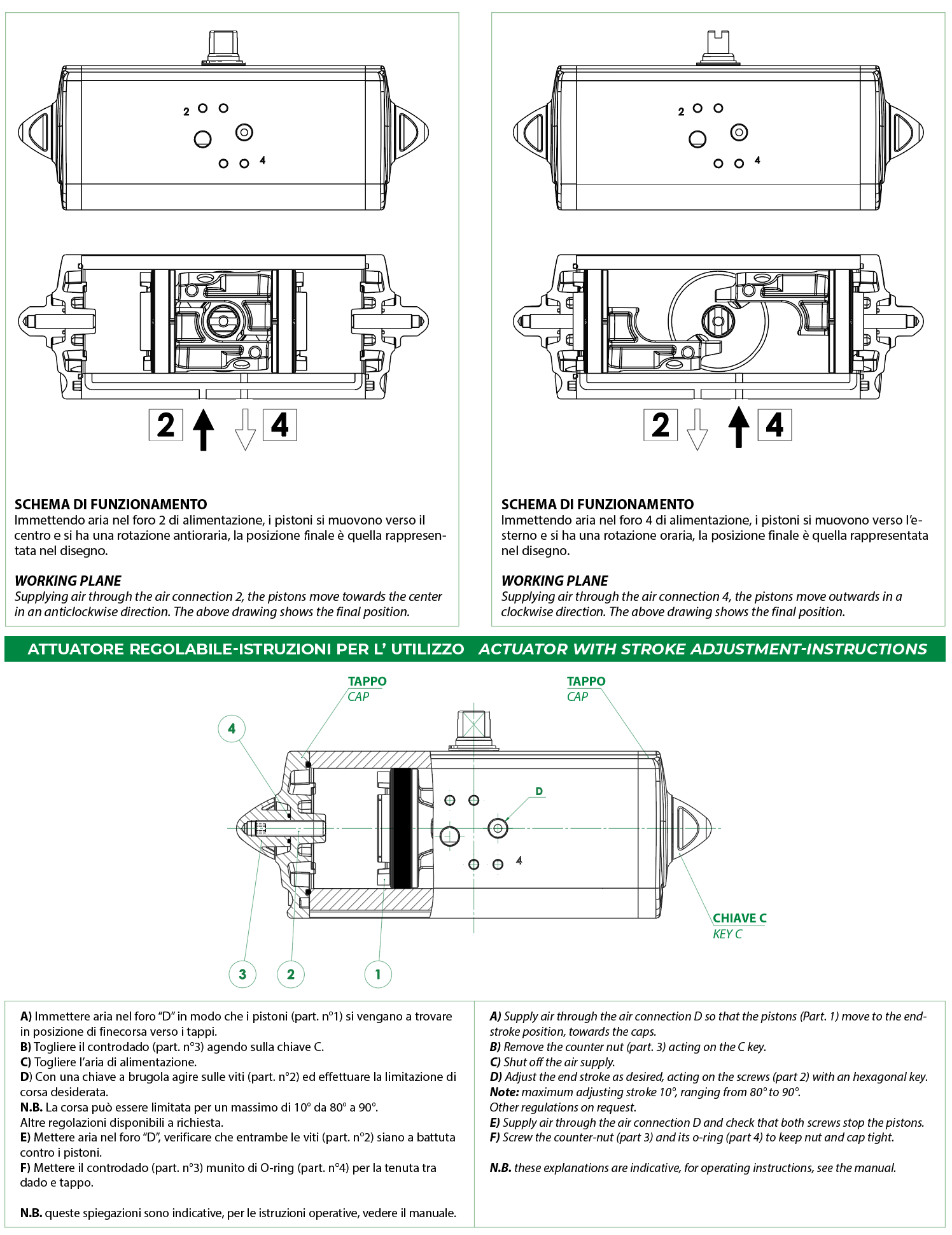
GD PNEUMATIC ACTUATOR OPERATING DIAGRAM
Drawings on the left = valve in open position Drawings on the right = valve in closed position
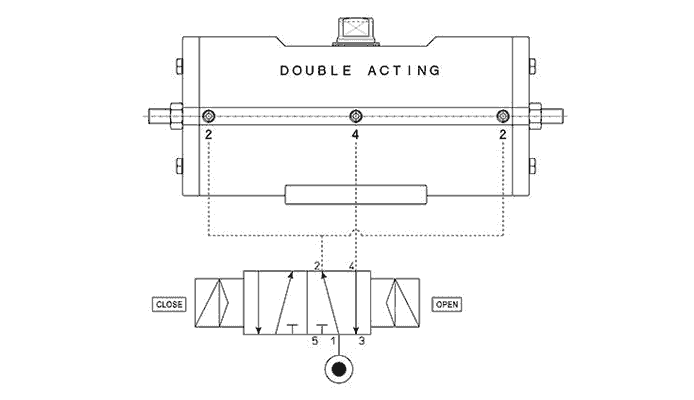
Typical air connection diagram Port 2 connects to the side chambers of the cylinder: by supplying pressurized air to port 2, the drive shaft of the Standard Double Acting actuator rotates anticlockwise to open. Port 4 is instead connected to the middle chamber: when it is pressurized, the shaft rotates clockwise to close. The remote control to operate the actuator must be performed by connecting the solenoid valve firectly to the standard interface of the VDE/VDI 3845 NAMUR actuator, or by means of pipes screwed onto the ports marked with numbers 2 and 4 (connected to a separate electrical cabinet). In accordance with the international standard ISO 5599-2, the position, location, orientation and shape of the actuator air port connections must be clearly identified and marketed using numbers 2 and 4.