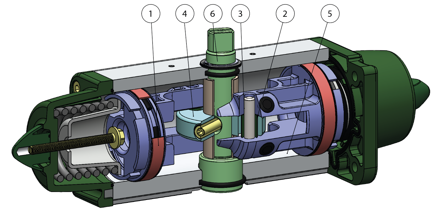
1.Energized and self-lubricated strips Less friction between piston and cylinder It prevents the bonding of the seal to the cylinder even after long periods of inactivity
2.Slots, bushes and pins made by steel with hardness higher than 50 HRC Higher resistance to the forces inside the actuator
3.Rolling friction between piston and slot Less friction
4.Scotch yoke with rolling friction (transforming rotary motion into linear motion using piston and shaft without teeths/gears) Reduced friction between piston and shaft with consequently less wear on the relevant parts Empowered Breakaway Torque (BTO & BTC) Smaller volume/size than rack and pinion actuators (with the same torque) therefore less space required for installation Less weight than the rack and pinion (-30% kg / Nm), with consequent savings on the construction sizing of the plant/equipment Lower air consumption compared to the rack and pinion actuators (-40% air cm3/Nm for Double Acting and -20% air cm3/Nm for Spring Return) therefore less load on the compressor or the possibility of using a smaller compressor's size. 5.Rolled cylinder Less wear of the energized ties thanks to the low roughness of the surface
From sizes bigger than GD15, NAMUR interface for solenoid valve is already integrated. No need for extra plate.
100% in- house manufacturing process technology Maximum control and accuracy in all the stages of the manufacturing process
ATEX Certificate Installation is allowed in a potential explosive environment
Up to SIL 3 Certified Guarantee of the high level of functional safety.
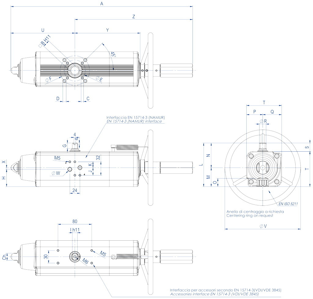
TECHNICAL FEATURES Torque from 30 Nm to 1920 Nm Mounting flange according to EN ISO 5211 F05 - F07 - F10 - F12 - F14 - F16 In compliance with EN 15714-3 Rotation angle: 92° (-1°, +91°) Torque: the return torque depends on spring action only notwithstanding the air supply. The spring is provided in four different sizes (see table) The actuator automatic closing takes place in clockwise direction by means of its springs In the code of standard version GSV actuators, it is indicated the size of the springs (6=5,6 bar) followed by the breakaway torque in Nm at 5,6 bar air supply. ATEX version in conformity with directive 2014/34/EU
WORKING CONDITION Temperature: from -20°C to +80°C (Special versions: high temperature= -20°C +150°C; low temperature= -50°C +60°) Air supply: 5,6 bar; maximum 8,4 bar Actuating media: filtered dry compressed air, not necessarily lubricated In case of lubricated air, either non detergent oil, NBR compatible oil, must be used.
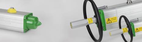
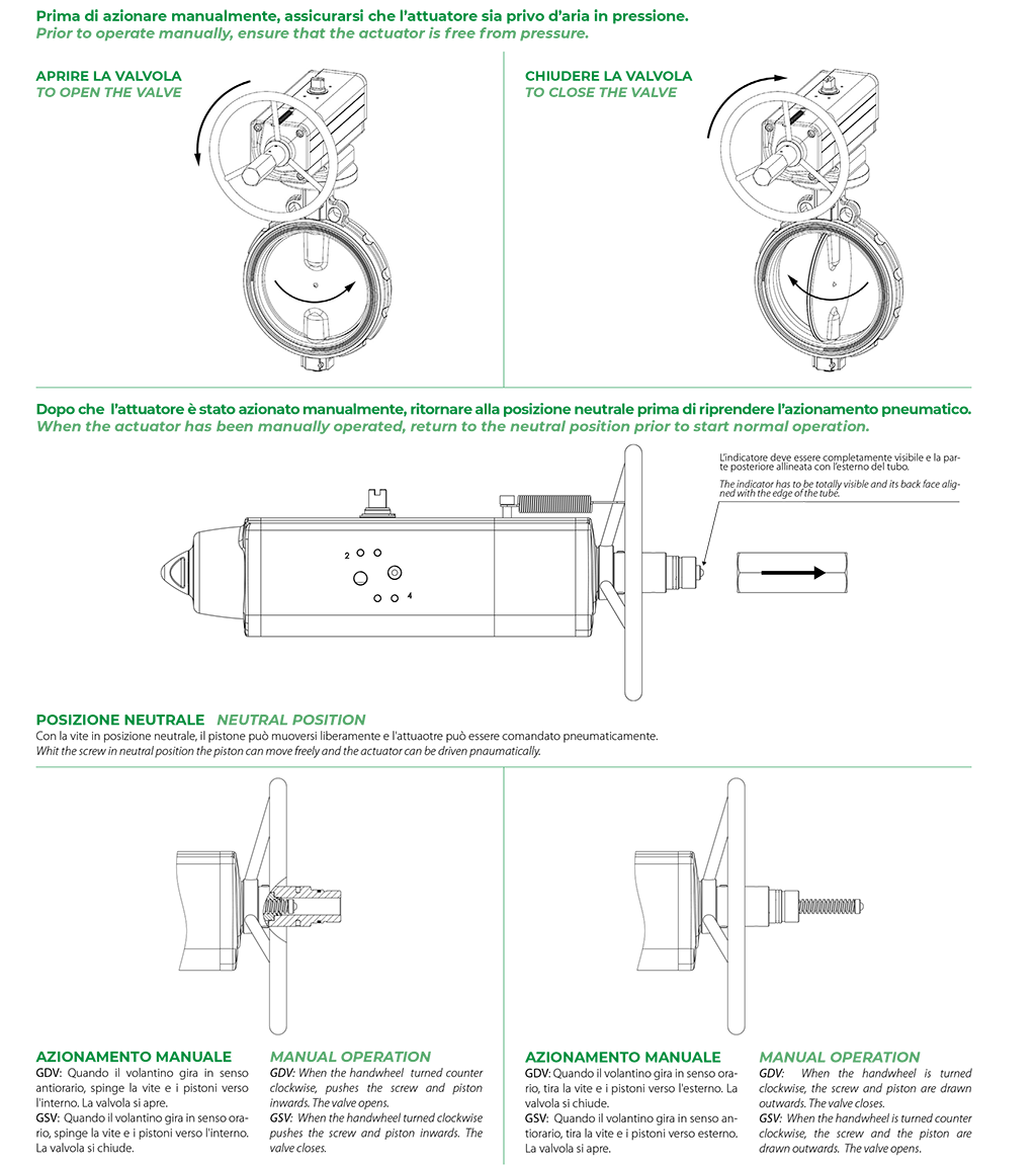
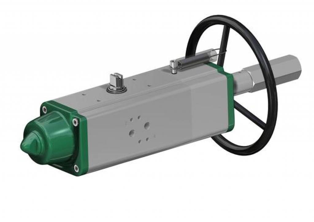
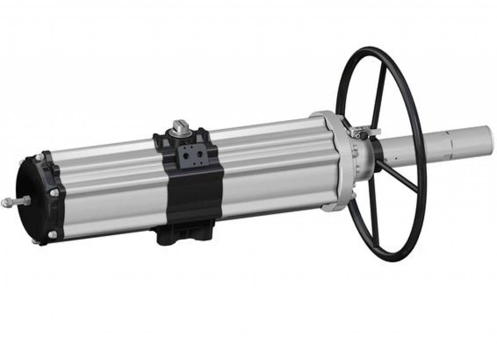
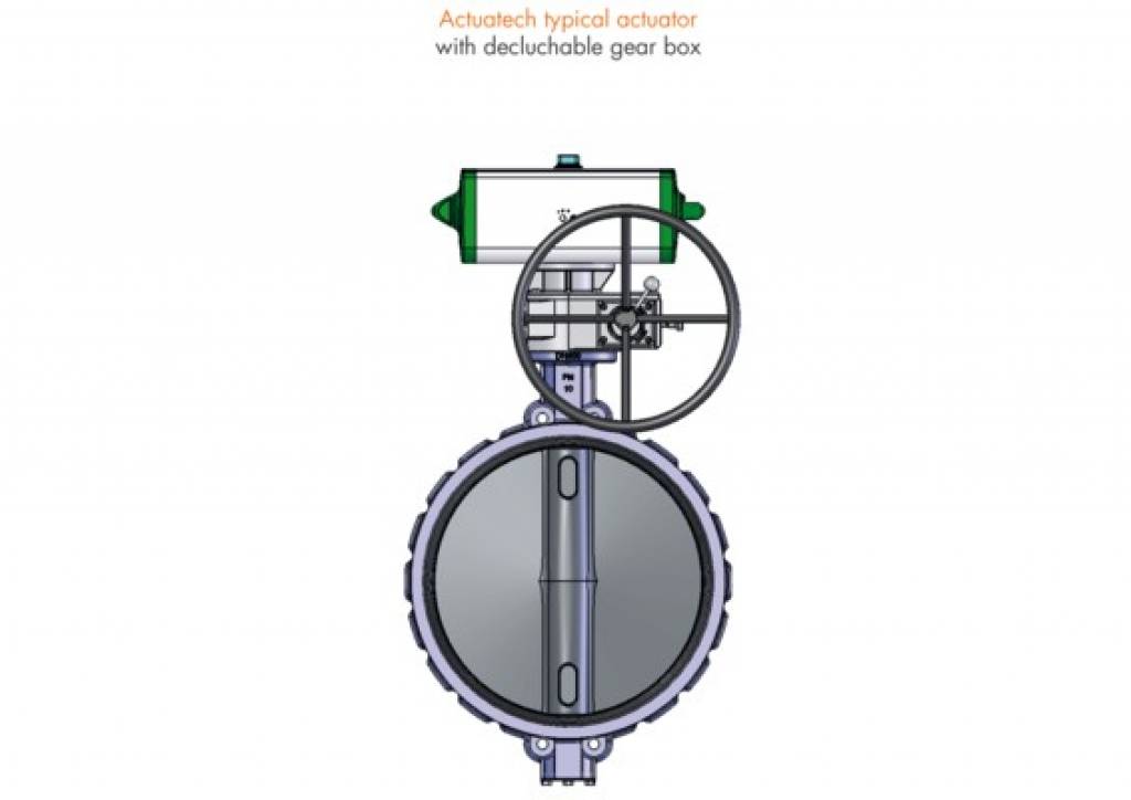
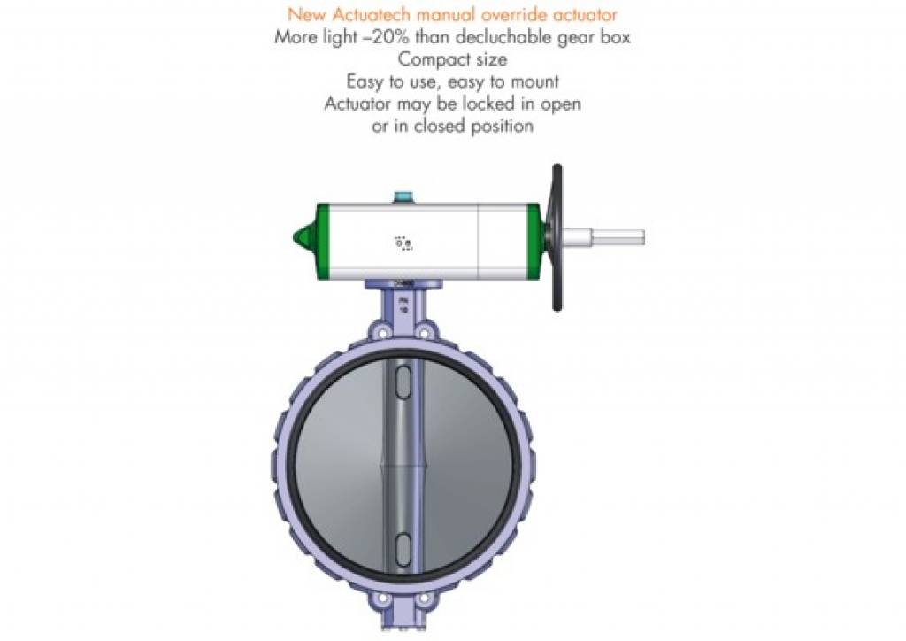
Once required the quarter turn pneumatic actuator can be equipped with a manual handwheel. The device can be integrated either in Double Acting and Spring Return versions. For the proper functioning of the system and for the mechanical integrity of the device is essential to ensure that the pneumatic actuator is disconnected from the power lines of compressed air before performing any operation using the manual handwheel. The manual handwheel acts on the transmission of the primary mechanical transmission of the pneumatic actuator and with torques applied to the handwheel according to EN 12570 it releases output torque of equal value of the nominal torque of the actuator.
GSV30 ÷ GSV960
DATA SHEET GSV30 ÷ GSV240
Code
GSV0030401S
GSV0030402S
GSV0053401S
GSV0060401S
GSV0090401S
GSV0120401S
GSV0180401S
GSV0240401S
Spare Seals
KGGI0016VX
KGGI0016VX
KGGI0060VX
KGGI0018VX
KGGI0019VX
KGGI0020VX
KGGI0021VX
KGGI0022VX
Size
GSV30
GSV30
GSV53
GSV60
GSV90
GSV120
GSV180
GSV240
ISO
F04
F05/F07
F05/F07
F05/F07
F07/F10
F07/F10
F07/F10
F10/F12
A
392,7
392,7
431,4
457,7
534,9
558,5
635
700,8
B
14
14
17
17
22
22
22
27
C x depth
M5x8
M6x9
M6x9
M6x9
M8x12
M8x12
M8x12
M10x15
D x depth
-
M8x12
M8x12
M8x12
M10x15
M10x15
M10x15
M12x18
E
42
50
50
50
70
70
70
102
F
-
70
70
70
102
102
102
125
G
13
13
13
13
16
17
19
19
H
33,7
33,7
40,8
42,8
52,5
56,1
58
57,4
J
18
18
18
18
18
18
18
16
K
14
14
14
14
14
14
14
16
I
10
10
12
12
15
15
19
19
L
90,4
90,4
103,3
107
137,5
141,1
148
164,9
M
37,7
37,7
44,8
46,8
56,5
60,1
62
72,9
N
52,7
52,7
58,5
60,2
81
81
86
92
O
16,5
16,5
19,3
19,3
24,8
24,8
24,3
29,5
P
32,7
32,7
38,5
40,2
51
51
56
62
Q
37,7
37,7
44,8
46,8
56,5
60,1
62
72,9
R
14,5
14,5
16,2
18
20,2
22,5
25,5
29
S
20
20
20
20
30
30
30
30
T
70,4
70,4
83,3
87
107,5
111,1
118
134,9
U
129,4
129,4
152,1
169,3
196,8
204,8
237
260,2
V
180
180
180
180
220
220
300
300
W (Gas)
1/8"
1/8"
1/8"
1/8"
1/8"
1/8"
1/8"
1/4"
X
4
4
4
4
4
4
4
-
Y
137,6
137,6
154,8
163,9
183,5
199,1
220,8
236,4
Z
263,3
263,3
279,3
288,4
338,1
353,7
398
440,6
Ch
13
13
17
17
22
22
22
27
N°of turns*
11
11
13
14
16
18
15
16
Weight (Kg)
3,2
3,2
4,5
5,3
6,8
9
11,7
15,2
Air (dm³/cycle)
0,17
0,17
0,3
0,33
0,55
0,8
1
1,5
* Theoretical n° of turns to close/open starting from neutral position.
DATA SHEET GSV360 ÷ GSV960
Code
GSV0360401S
GSV0480401S
GSV0480402S
GSV0720401S
GSV0720402S
GSV0960401S
GSV0960402S
Spare Seals
KGGI0023VX
KGGI0024VX
KGGI0024VX
KGGI0025VX
KGGI0025VX
KGGI0026VX
KGGI0026VX
Size
GSV360
GSV480
GSV480
GSV720
GSV720
GSV960
GSV960
ISO
F10/F12
F10/F12
F14
F14
F12
F14
F12/F16
A
810,1
842,4
842,4
1035,4
1035,4
1067,7
1067,7
B
27
36
36
36
36
46
46
C x depth
M10x15
M10x15
M16x24
M16x24
M12x18
M16x24
M12x18
D x depth
M12x18
M12x18
-
-
-
-
M20x30
E
102
102
140
140
125
140
125
F
125
125
-
-
-
-
165
G
19,5
19,5
19,5
19,5
19,5
18,5
18,5
H
61,5
78
78
86,5
86,5
99,2
99,2
J
16
16
16
16
16
16
16
K
16
16
16
16
16
16
16
I
22
24
24
27
27
32
32
L
178
198
198
216
216
237,7
237,7
M
78,5
93,5
93,5
101,5
101,5
114,7
114,7
N
99,5
104,5
104,5
114,5
114,5
123
123
O
29,5
38,5
38,5
38,5
38,5
48,5
48,5
P
69,5
74,5
74,5
84,5
84,5
93
93
Q
78,5
93,5
93,5
101,5
101,5
114,7
114,7
R
31,8
36,5
36,5
41
41
46
46
S
30
30
30
30
30
30
30
T
148
168
168
186
186
207,7
207,7
U
306,6
324,1
324,1
399
399
414
414
V
350
350
350
400
400
400
400
W (Gas)
1/4"
1/4"
1/4"
1/4"
1/4"
1/4"
1/4"
X
-
-
-
-
-
-
-
Y
282,3
297,1
297,1
365,6
365,6
382,9
382,9
Z
503,5
518,3
518,3
636,4
636,4
653,7
653,7
Ch
27
27
27
36
36
36
36
N°of turns*
19
20
20
25
25
26
26
Weight (Kg)
19,5
28,1
28,1
38,8
38,8
50,6
50,6
Air (dm³/cycle)
2
2,8
2,8
4,2
4,2
5,9
5,9
* Theoretical n° of turns to close/open starting from neutral position.
GSV1920
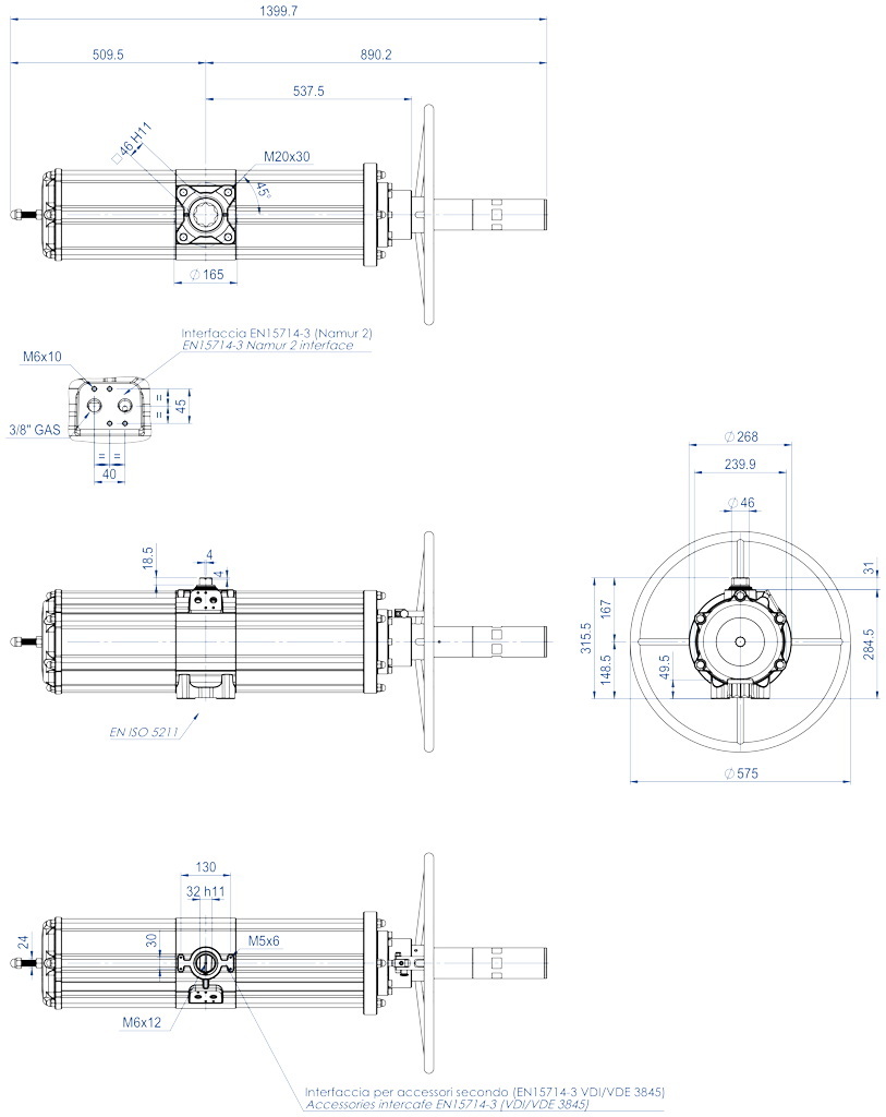
DATA SHEET GSV1920
Code
GSV1920E1608A
Spare Seals
KGGI0230VX
Size
GSV1920
ISO
F16
N°of turns*
30
Weight (Kg)
91
Air (dm³/cycle)
12,5
* Theoretical n° of turns to close/open starting from neutral position.
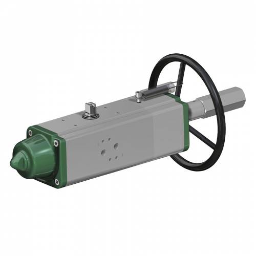
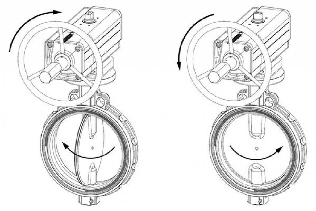
Working plane pneumatic actuator with integrated handwheel
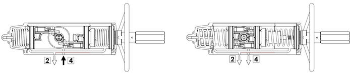
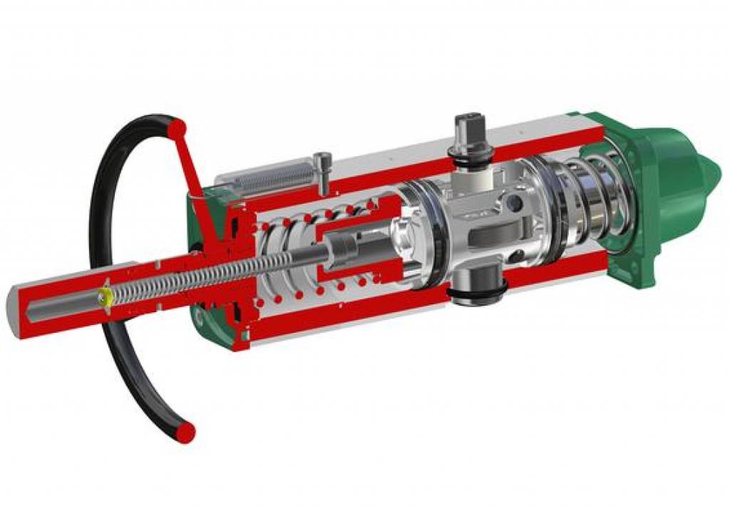
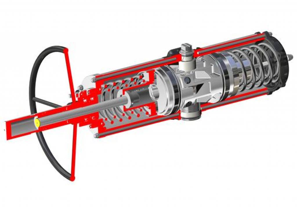
Actuator operating diagram with integrated manual override
Drawings on the left = valve in open position Drawings on the right = valve in closed position
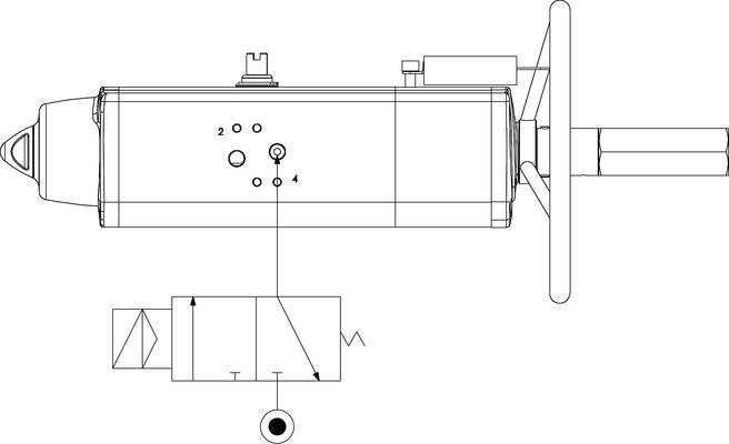
Typical air connection diagram The pistons of the standard GS actuators are mounted as shown above. Although the spring force is small, the geometry of the mechanism provides more torque at the end of stroke. When the actuator is in the valve open position and the springs are fully compressed, the end stops can be adjusted with precision. Reverse acting spring return actuators are required when the valve needs to open automatically in the case that the pressurized air or power supply is turned off. In reverse acting actuators, the pistons are inserted into the cylinder in the same way as in the Double Acting version and, due to the force of the spring, the actuator opens normally. Caution. The normal torque performance in the reverse acting version, due to its construction, is different from that of the standard version. Caution. To prevent dust or dirt from being sucked into the actuator chamber during spring action, install a filter on port 2. Port 4 is connected to the middle chamber and, when pressurized, the drive shaft rotates anticlockwise to open. In accordance with the international standard ISO 5599-2, the position, location, orientation and shape of the actuator air port connections must be clearly identified and marketed using numbers 2 and 4.